Controlling an Ellard garage door controller with a Shelly 2.5
The following blog contains details of messing around with mains voltage electrics. This post is intended as entertainment and an aide-mémoire for the author. Please do not treat it as a “how to” guide. Mains voltage electricity is dangerous, and if in doubt, you should leave dealing with it to a qualified professional.
As has been mentioned, I have an electrically operated roller shutter on my garage. Most Americans, I suspect, would consider this entirely unremarkable.
Here in the UK, though, even new build houses in 2023 usually have an up-and-over garage door you have to physically heft open and shut yourself. Then again, since their garages aren’t wide enough for 21st century cars, it doesn’t really matter…
Since there’s no access down the sides of my house, you have to go through the garage or the house itself to get to the back. So for the benefit of the window cleaner and such, it’s useful to be able to open and close the garage door when I’m not there.
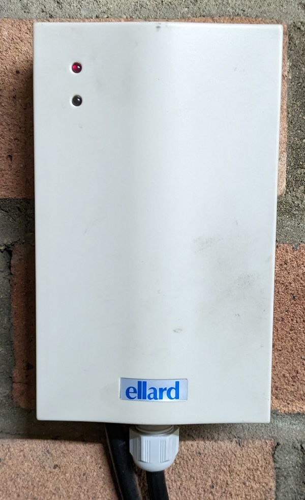
Wherever electrically operated doors do exist in the UK, they all seem to use the same type of controller - it’s made by Ellard and it looks very similar to this:
It comes with a couple of radio remote controls which you hang on your key ring and use to open and close the door from the outside - ideally from the comfort of your driver’s seat. However, their range is limited to about three metres on a good day, and I need something that works from about three miles away.
My first attempt at remote control involved a Raspberry Pi with a relay board, and those terminals shown on the right of the photo below:
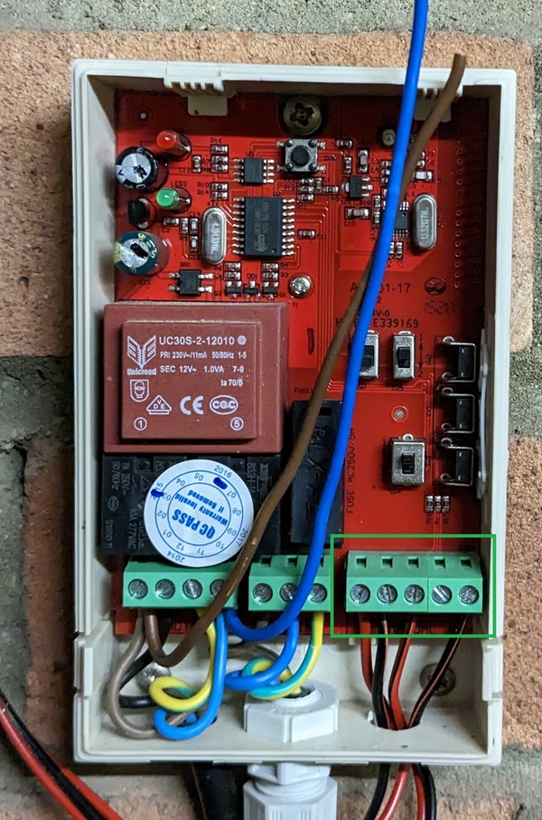
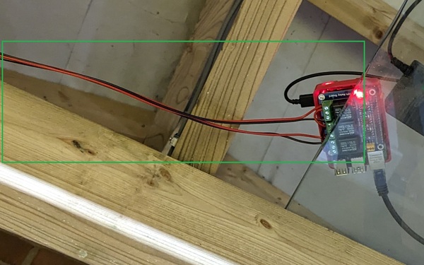
These are designed for connecting an external key switch (see wiring diagram), so they happen to be just the thing for controlling the door with a couple of “dry contact” relays. The terminals operate on 12V DC and you short U (up) or D (down) to ground (G) with a relay in order to move the door up or down. The limit switches in the motor will (at least in my case) prevent it from damaging itself or the door by over-opening or over-closing, so you don’t need to get your relay timings down to the second - just hold up or down for about 5 seconds longer than the door takes to open or close, and Bob’s your uncle. And let’s not get hung up on the low voltage wire strung messily across the garage:
However. This solution sort-of works, but it’s painfully manual. I have to SSH to the occasionally changing IP address of my house on a non-standard port number, run the scripts, and more often than not reboot the Pi to reset the state of the relay board between attempts. I’m not sure what I’m doing wrong, but trying to pull this off on a mobile phone while the window cleaner silently fumes over the speaker doesn’t really cut it.
So, what’s the answer for a more self-contained solution which is a bit more slick? Enter Shelly. This is the geek’s home automation brand of choice, and they make various relay switches which are controlled via WiFi.
In this case, we need the Shelly 2.5 which has two outputs and even has a dedicated “roller shutter” operation mode.
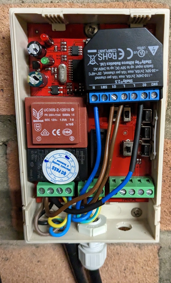
The icing on the cake is that this will physically fit inside the Ellard box and still allow the lid to go back on, which means it can be powered from the incoming feed and we need no extra cables trailing around the place:
Of course, the box is made of plastic in order to not block the radio signals from the remotes, which works out nicely for the Shelly being able to hop on the WiFi.
It’s important to read the instructions and wiring diagrams carefully. My past experience with the Shelly 1 led me to suspect that I could power it temporarily from a cut-off USB lead while configuring it, but whilst one can get away with that on the smaller model, the 2.5 won’t boot from 12V DC, so unless you happen to have a bench power supply or similar, you end up making a “wire of death” in order to get the thing powered so you can do configuration before installing it in the final location:
I removed the plug from the bare cable when I was finished - even if the only person likely to find it lying around is my future self, better safe than sorry.
I had hoped the Shelly would provide two dry contact relays which could be connected to the DC contacts previously used by the Pi.
However, if I’d read the data sheet properly it would have been clear such is not the case. The two outputs will run at the same voltage you’re putting into the thing, so in my case, if it’s going to run off 240V AC in the Ellard box, outputs 01 and 02 will be at that voltage. So using the DC contacts was out.
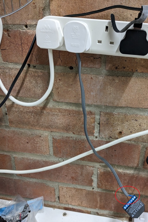
However, as you can perhaps see from the picture of the final wiring above, I worked out that I could link the “rotate left” and “rotate right” wires going to the motor directly to the Shelly. So it’s effectively acting in its own right to control the motor at mains voltage and bypassing the Ellard. Not as nice, and very important to get the terminals done up tight (loose wires cause fires). I used the inner cores from some 1mm twin and earth cable to put the links in - the speaker wire used for the DC wouldn’t be suitable for carrying a theoretical max of 10 amps of AC current.
This does mean that the Ellard and the Shelly could end up giving contradictory instructions to the motor, but in practice I’m not too worried about that as I’m the only one with access to either means of control.
As you can perhaps also see, I sleeved my blue link black to indicate it has the same function as the black in the three core going out to the motor, i.e. it’s not a neutral, it’s a switched live. Perhaps it would have been better to sleeve them both brown, but for now I’ve followed suit with what the original installer did.
Then again, I was putting it all back together when I noticed that both the Shelly 2.5 and the Ellard controller are very clear on their data sheets that 10A is the maximum input. Which makes it disappointing that someone had put a 13 amp fuse into the plug on the unit. The power consumption measurement in the Shelly implied that the motor would have been happy with a 3A fuse, but in reality that wasn’t sufficient for it to lift the weight of the shutter.
Fortunately, I dug a bit deeper into the garage and found a 10A fuse in the right shape to fit, and at last the job is done.
On the software side, you can trigger moving the shutter up and down from the Shelly’s web UI if you’re on the same WiFi network as it, but you can also link it to Shelly’s cloud. You don’t have to, and the purists wouldn’t dream of such a thing, but my pragmatic position is I’m willing to take the risk for the convenience.
Here’s the app in action:
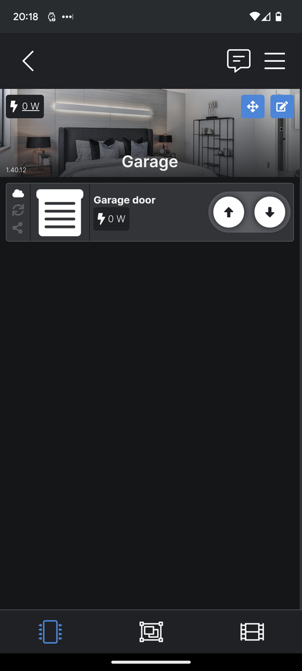
Obviously this works from other networks, which is to say anywhere in the world with Internet access.
And at least, if Shelly goes bust, I can still do it all myself the hard way, rather than being left with a useless device.
A proper result - the first Shelly to go in at home, but almost certainly not the last.